CS:R and CS:L Shaved Utility Arms
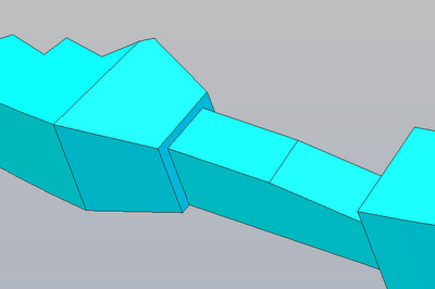
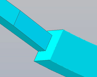
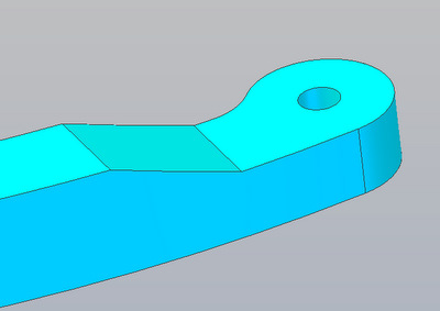
While fitting the engraved skins onto my CS:R Frame I encountered what is apparently a well known problem: Spec Design utility arms, both CS:L and CS:R, will not swing out thru the skin openings unless either the skin opening is enlarged, or the back edges of the utility arms are shaved (tapered). For more details see the following Forum Post: A&A Skins and Utility Arms I've done two things to attempt to deal with this problem. The first was to enlarge the Utility Arm openings in the Single Layer Engraved Skins that I'm offering by .0625 [the width of the panel lines]. The second was to shave .0625 off of the back edge of the arms where they bind |
|
|
|
|
|
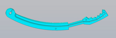 |
CS:L Shaved
Utility Arm This is an update of my original CS:L Arm. I've added the tunnel if you want to install a light at the Arm Tip and a screw hole for a mounting screw to hold the arm position on a .25 shaft. |
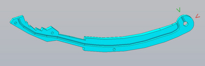 |
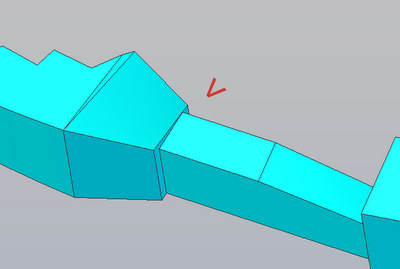
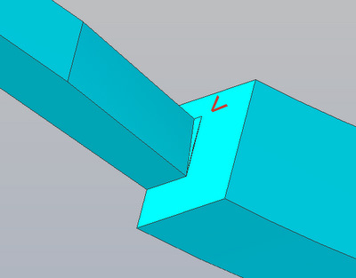
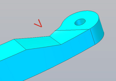
CS:R Shaved
Utility Arm This is an update of my original CS:R Arm. The tunnel is the same as before while the mounting screw was moved to the new (green arrow) position from where it was (red arrow) to enable better access with the arm in the closed position. |
| The
images above are linked to 3D .pdf versions. Click on them to load. Clinc HERE to download a .zip file of the 3D models of the (half) arm in .stp (STEP) CAD format. To 3D print it you'll have to mirror the model to get the other half and convert the halves to .stl format. |
|
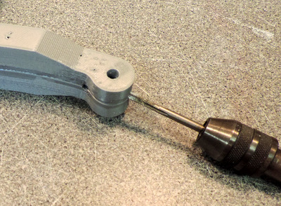
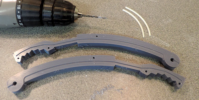 The utility arms have 3 pins, made from 3mm filament, to hold them in alignment while they are being glued together. If you are going to put a LED at the arm tip extend the channel thru the tip. |
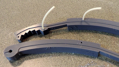 The arms that I ship to customers are already drilled for the filament. |
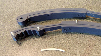 cut the pieces short as there's not much depth in the arm halves. |
 make sure all 3 pins line up and that the edges are together before you clamp them |
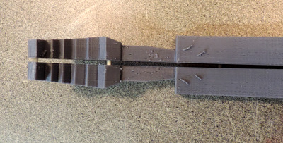
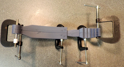 Clamp the halves together, insert a 1/4 in shaft (or a bolt) to act as a fourth alignment point. Keep in mind that Utility Arms are mostly hollow. You only need enough tightness on the clamps to keep the pieces in good contact while the glue sets. Don't crush the parts. |
 there's a hole for an anchor screw to hold the Utility arm in place but still permit some up/down adjustment As noted above, the screw location has moved. |
 |
Until you are ready to do the final position adjustments, just center the Utility Arm and tighten the screw to hold in position. DO NOT OVER TIGHTEN THE SCREW AS YOU CAN STRIP THE THREADS. |
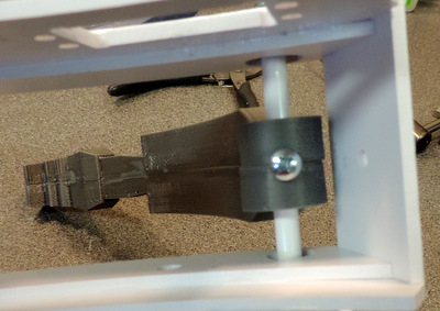
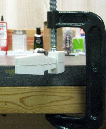
 Above: I assembled an early prototype print. It didn't have the alignment pins or the finer layer height. Note the bolt to align the pivot point. I used Weldon 16 to glue the two pieces together. Right: you can see the glue joint. I used a C Clamp to hold the arm to my workbench |
 |
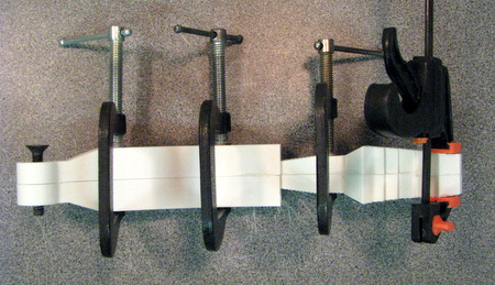
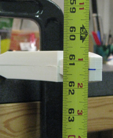 I hung a tape measure from a ceiling rafter to provide a visible reference |
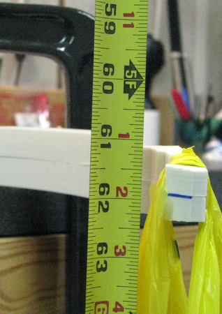 then I hung a weight from the tip of the arm. I read the deflection at 5/8 of an inch. |
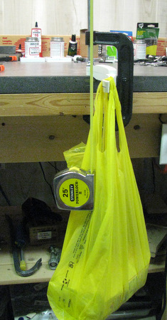 Here's a longer view of the test setup with the weight in the bag |
 And In the Bag, 5Lbs of Sugar!!! |
| What
have we proved? 3D printed utility arms will flex about 5/8 of an inch
under a 5lb load. That doesn't make them indestructible. But it does show they are not fragile. |
|
| Home |