Front & Rear Logic Displays

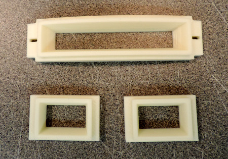
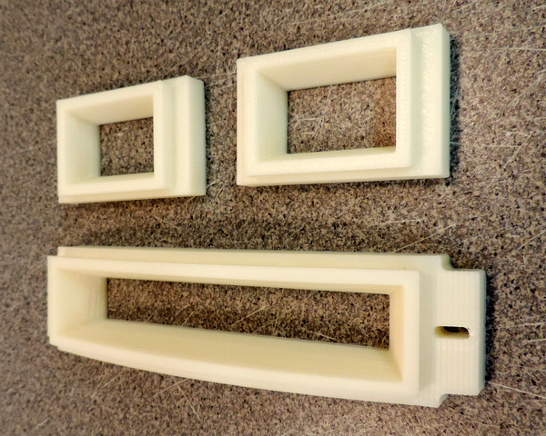
One of these is used in the Rear of the Dome
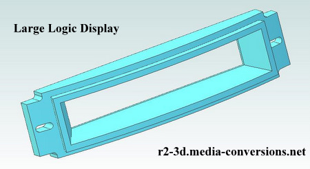
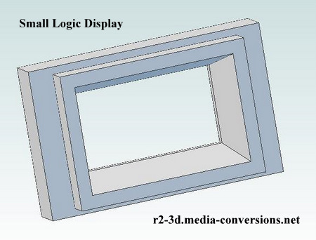
Two of these are used in the Front of the Dome
Click on either of the images to open a 3D .pdf version of the design.

While working on 3D design of this part, I came across 3 problems on the R2BC drawing I was working from. It's the April 2005 version, let me know if there is a revision, I could not find one. Refer to the R2BC .pdf drawing, parts of which are reproduced here.


The first two involve the angles shown on the drawing.
The 28 degree angle at the top really should be 27.64 degrees, while the 59 degree angle at the bottom should be 58.89 degrees. While they are small differences a part made using the angles will not have the matching measurements
which I'm assuming are correct.


The third problem is simple math.
The bezel rim depth is 9.125 - 8.937 = .188 (as noted on the R2BC .pdf)
At the centerline, the part depth is .812 as shown to the left. This can be verified separately, using the construct above.
Given those dimensions, the bezel body
is .812 - .188 = .624 not the .625 shown.
This could be a round off error,
but in any case is an inconsistency.

You can download models in STEP AP203 (.stp) format in English (inch) units as well as in 3D.pdf format. I've also included the original R2BC .pdf drawing for the Large Logic Display and the illustration of the wrong angles from above.: click here.

Here's what 3D printed parts look like


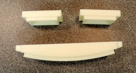
The top edge of the Large Logic Display is printed with a .1mm layer height to minimize the stair stepping
that is visible on the mounting ear which was printed with .3mm layer height


Home