You want to do it now to prevent things like the extruder head, or the dial indicator I'm going to use for setup, from crashing into your boro glass surface.
A1 Alignment
The Assembly Wiki has some information posted by Eugene B on the alignment process he used. TL has posted a T1 Tuning Instructional Video, announced in this forum thread that includes both alignment and first print information. Please review both. |
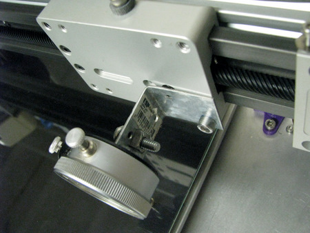
Second, you should install a properly sized bolt for your Z Endstop.
Page 4, step 44, of the Aluminatus TrinityOne Assembly 2003-06
document indicates that your Z
Endstop bolt should be an M3 x10 or x25. The Assembly Wiki,
under Make Z-axis endstop switch functional,
reveals that it really needs to be 40mm long. I didn't have
anything like that in my "goodies bag" of parts so I substituted a 1.5
inch 4/40 bolt. You want to do it now to prevent things like the extruder head, or the dial indicator I'm going to use for setup, from crashing into your boro glass surface. |
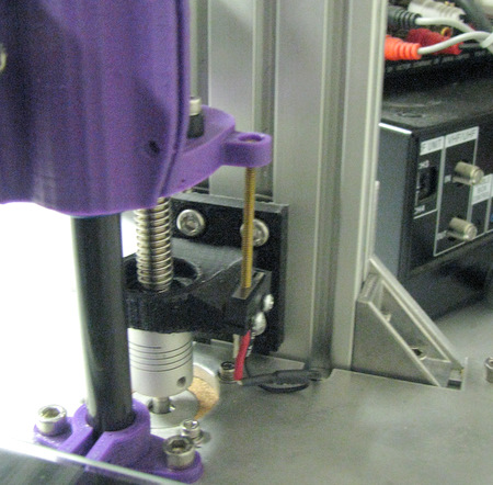
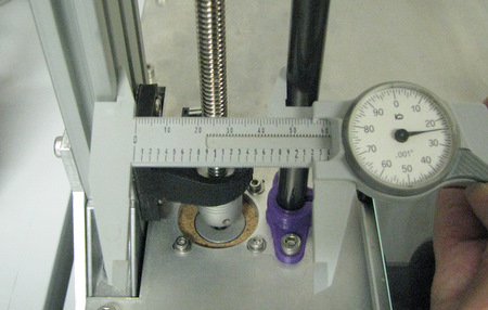 Start by measuring the distance from the smooth rods to the edge of the gantry at the bottom (where it's fixed) | 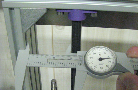 Then adjust the Rod Clamps at the top of the Gantry so the spacing is the same. |
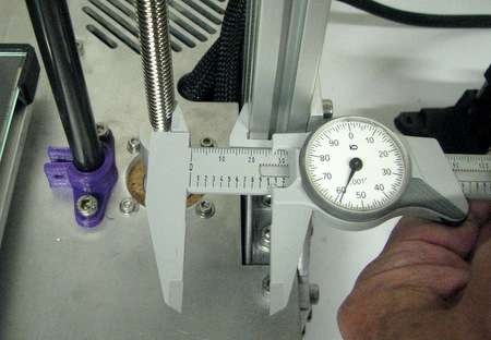 next. do the same for the Z-axis feedscrews |
 tighten the bolts that hold the antibacklash nuts on the X-ends so that the spacing is the same. |
| Review Eric's Tuning Video. I'm going to suggest
you fine tune the feedscrew positions by moving the stepper motors. But
I'm also going to suggest that you do that after you have the x-axis
level and the Xends bolted in place. |
|
 |
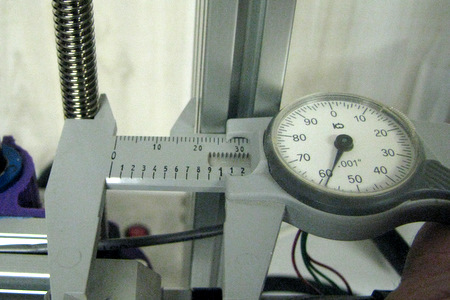
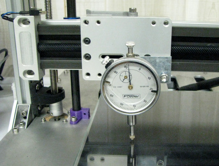
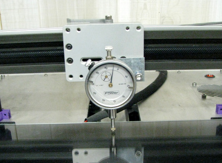
 Start at the center of the bed and set the dial to indicating zero. |
 Move to one edge of the bed and take a reading. We are .011 high on this side. |
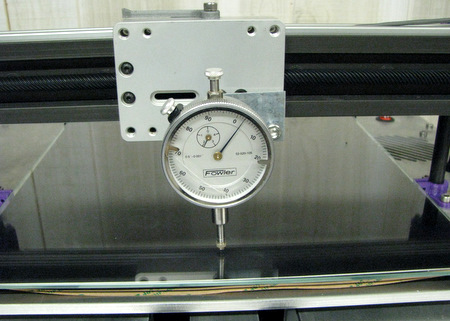
 Move to the other edge. Here we are .009 low on this side. |
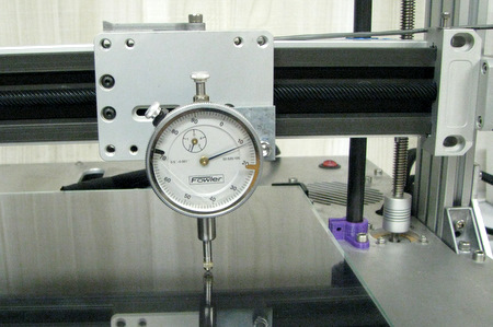
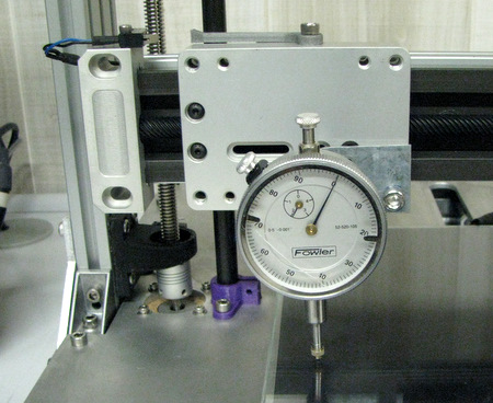 Manually turn the feedscrew on this side until you read zero. Then go to the opposite side and adjust the feed screw there. |
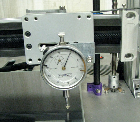 Repeat the process, going from side to side until the X-axis is level. |
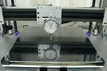
 Again, starting from the center of the bed and a zero setting on the dial this time move the bed in the Y direction |
 Take measurements at rear of the bed |
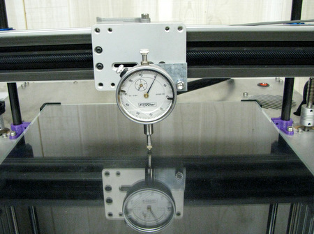
 And again at the front of the bed. |
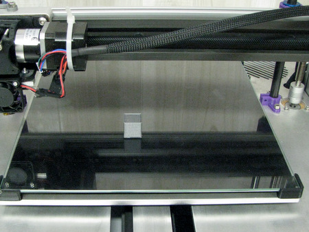
Unless you put in bed leveling screws of your own design there are no "adjustments" to level the bed. If you look closely, you'll notice that I have not yet attached my Kapton heater to the heat spreader. (You can see it drooping down in the center in the picture at left.) It's the reason my bed isn't level in the Y-axis. I'll postpone any Y-axis bed leveling (by shimming the corners) until after I attach the Kapton Heater. |
 The original print had a one extruder wide ring around the cube. | 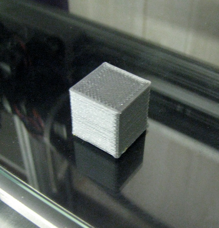 |
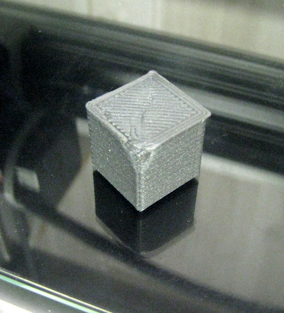 | The results were far from perfect. I had a first layer adhesion problem with what was the rear corner of the cube. My 20mm (.787 in) cube measures .778/.780/.778. The 3mm (.118 in) PLA filament I used measures .108/.114/.115 (end/middle/end) for a .112 average. So it's not surprising that the cube is undersized! However, considering the un-optimized state of affairs for this attempt, I consider this "First Print" to be a SUCCESS!! |
| Home |