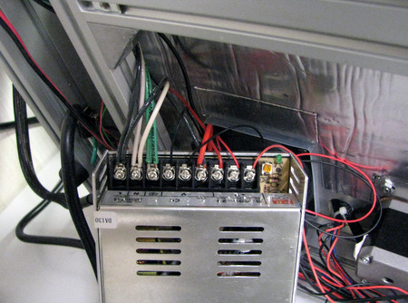
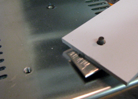
Phase 1 Rebuild
The first step in my re-build is to move the electronics out from under the printer baseLeft : Before Below: After |
|
We'll also re-purpose the power supply to use for our AC connections |
It's not easy to see, but that's a black, and a white wire on the AC outlet. (both covered in heat shrink) I'm verifying it's wired correctly and the black is the "hot" wire. |
I added a 10 Amp circuit breaker/switch to the back of the power supply. |
Two important steps. Remove the glass bed and un-plug your printer!!! |
|
Find enough space to turn it on it's side. Unscrew the bottom panels and remove the power supplies from the panels. |
Document where the wires are going. The power supplies are made by Wei Hao. Their data sheets can be downloaded from their website PS250 and PS400. |
For both power supplies, the RAMPS board, and the FET that drives the heated bed. If you have a B1 printer you'll find that the ardunio fan (12v) is wired in series with the J-head fan (12v). Make some drawings of your own so you can connect things back together later on. |
The mounting screws are too long to be used on sheet metal alone. Here I've put in a plastic spacer. That also prevents the ventilation slots from being blocked. |
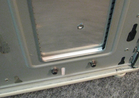
Added washers under the screw heads make sure that they don't extend too far into the power supplies |
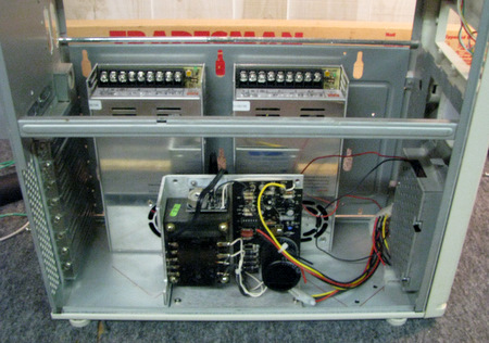
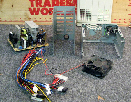
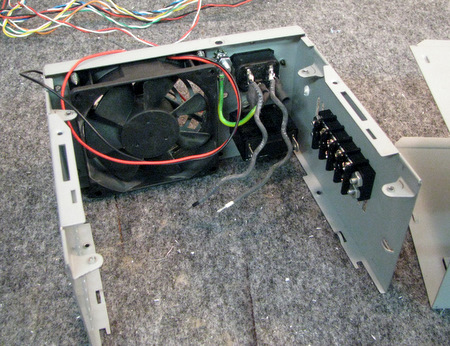
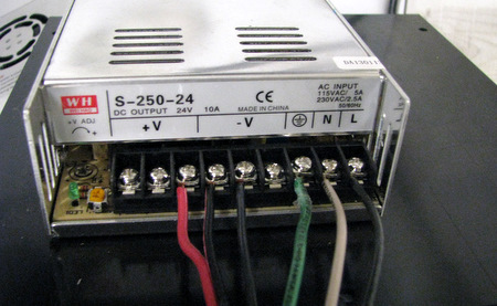
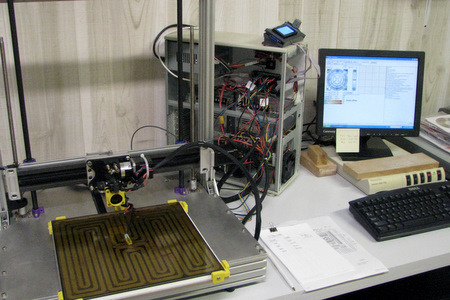
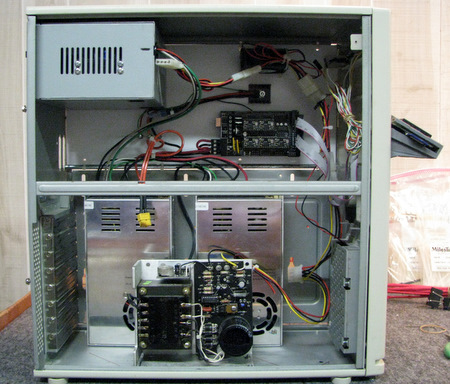
I added a 12v power supply. I've got's lots of 12v fans. There are 3 in the chassis. One in the old power supply (blowing out) one at the bottom front (blowing in) and one blowing on the RAMPS to cool the stepper drivers. I've converted the Deck fan to 12v and the J-Head fan was already 12v |
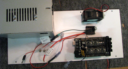
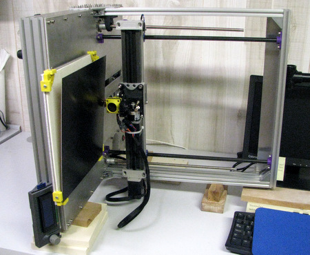
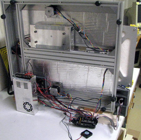
The RAMPS is mounted on a plastic panel in the top of the chassis, along with the FET driver for the bed and a cooling fan. I added some standoff's for the FET wiring to anchor to. All of the fans will use PC style molex power connectors. |
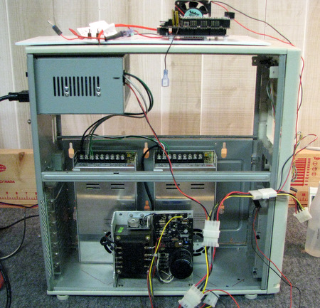
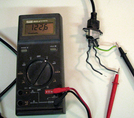
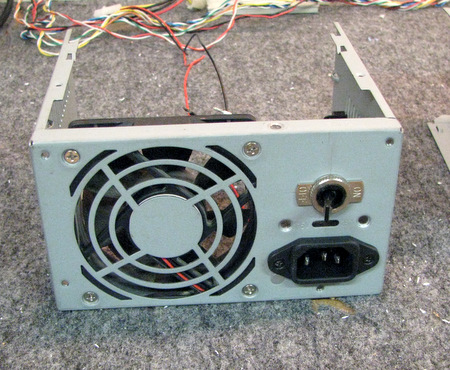
Testing the AC and Fan connections before proceeding further. | 
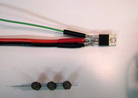
re-wiring the FET. nice heavy duty wire on the power leads. The FET is an AOT240L. The data sheet can be found here. From top to bottom, above, the connections are Gate, Drain, and Source. Source goes to the PS400 ground. Drain to the Bed. The other bed connection to the PS400 +24V. |
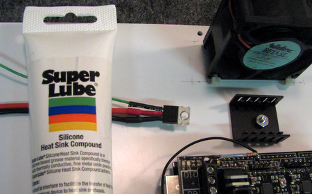
Heat sink compound used on the FET to heat sink joint. I added the heat sink since I'm not mounting the FET to the metal chassis. Note that the mounting tab is at 40V and was insulated on the A1 | |
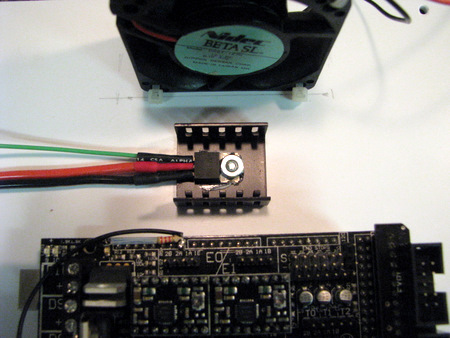
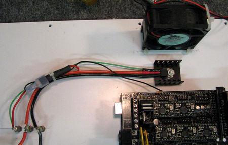
Above: wiring to RAMPS connection. I re-used the original insulated spade connection. Right: completed power wiring for the Bed Heater. That's an XT60 connector it can handle the current. the two bare wires go to the PS400 power supply. | |
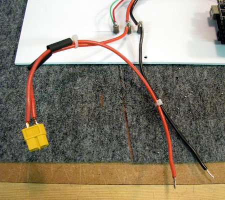
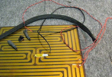
This is my old Kapton Bed Heater. It turned out to be very easy to unsolder the older 18 Ga wire and replace it with heavier 16 Ga wire. | |
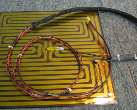
NOTE: there is currently a thread on the A1 Forum "Bed caught fire ..." that you should consult for the latest information on Bed Wiring for the B1 series of printers. | |
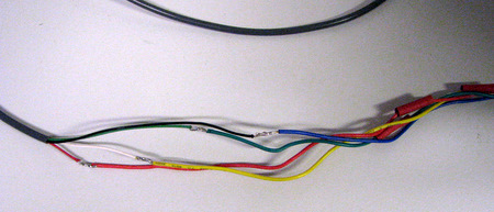
I also had to "extend" my stepper motor cables. I purchased some 4 wire 22 Ga cable. Here are the staggered splices between the Motor and the Cable. | 
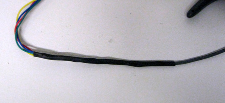
Each splice is insulated, then a second piece of heat shrink covers the set of splices. |
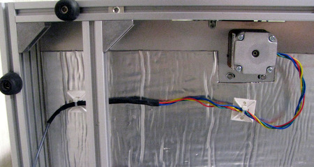
I used adhesive anchors to route the wiring out the rear of the printer and keep it away from the moving parts. |
This is just a "functional" test so I've left the side panels
off of the chassis and routed some of the wiring directly across the
back of the printer. I'm not intending to move anything more than a few
inches. First Test Results: Everything went smoothly. I had the extruder motor in plugged backwards, but that might be a symptom of it being mounted on the right. I also had one of the end stop switches in backwards. Both the extruder and the heated bed came up to temp and leveled off as expected. One unusual symptom. I don't know if it is related to the new bed wiring (16Ga wire instead of 18Ga) or if it's because it's out where it can be heard, something is making noise when the bed cycles on. I thought it was the RAMPS, but it might be the power supply going into current limiting. |
|
Second Test:
I'm going to conduct a second test with minimal connections to the
RAMPS. Just the 2 thermistors (otherwise you get a Min Temp error) and the Bed Heater. I'm going to attach a scope to measure the Bed voltage (and therefore the bed current). Results:
I thought the noise might be generated by the power supply going into
current limiting. It's not, even though it ought to be, and the spec
sheet says it will. I'm seeing a clean +5 volt signal on the gate of
the FET. The red RAMPS FET-on Led is coming on, when it does, I get a
'rattling' noise. There's nothing else, except the thermistors,
connected to the RAMPS. Does anyone else hear a noise as their bed heater cycles on/off??? my wiring for the bed heater is as follows: PS400 +24 to bed. Bed to FET-drain (center pin above) FET-source (bottom pin above) to PS400 ground PS400 ground to PS250 ground PS250 +/- 24v to RAMPS RAMPS drive signal (tacked on wire) to FET-gate (top pin above). The heated bed runs up to temp (I'm using 110 C in the tests) and holds. When power is applied to the bed the RAMPS is rattling. -- I'm stumped! | |
After the functional test I modified the holder for the RAMPS front panel display so it could be attached to the PC chassis's front bezel. I'm not happy with the way it came out, but it will do for now. |
Home |