Or you can download a STEP AP203 (.stp) version
of the design file.
You can download a newer model of the CS:L Octagon Port from the Astromech 3D file Droidwiki:
https://astromech.net/droidwiki/Utility_Arms_CSL
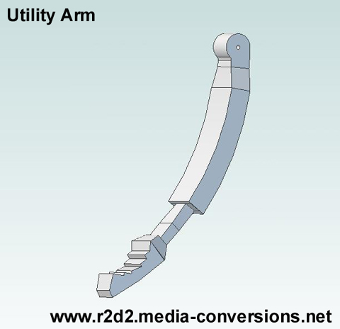
Utility Arm
There is a Google SketchUp file (.skp) available for the Utility Arm. Unfortunately the Alibre 3D CAD softare I'm using can't import that file type. So I created my own version of the Utility Arm, derived from the R2BC Drawings. The hole at the pivot point is nominally 1/4 inch. If you want an arm with a different size hole let me know and I can make one for you.|
|
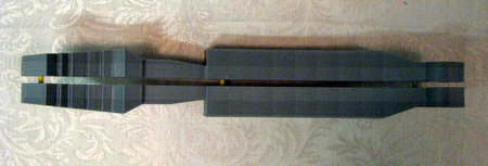
Click on the
image to open a 3D .pdf version. Or you can download a STEP AP203 (.stp) version of the design file. You can download a newer model of the CS:L Octagon Port from the Astromech 3D file Droidwiki: https://astromech.net/droidwiki/Utility_Arms_CSL |
 |
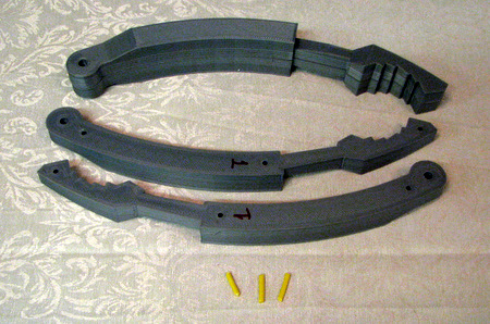
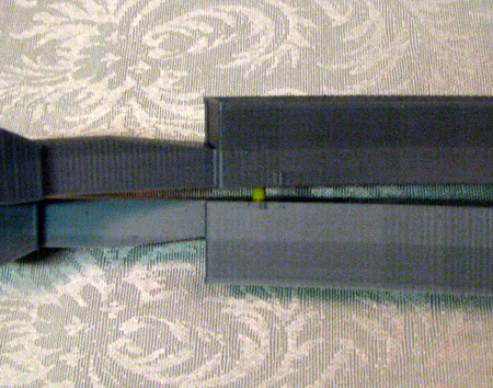
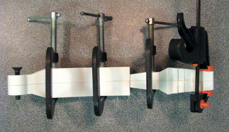
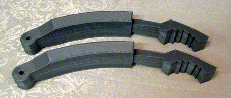 You get a set of 2 Utility Arms. Each Arm is a pair of half arm pieces. The arms have alignment holes and pieces of ABS filament are used as the pins to hold alignment while being glued. |
 |
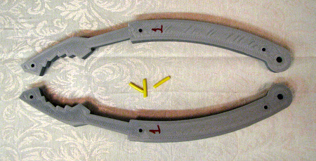 |
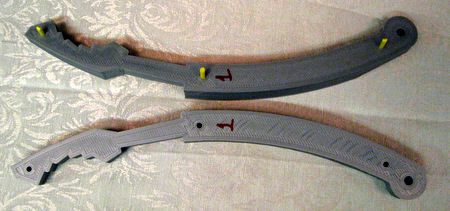 Insert pins. If there is a shorter pin put it in the hole at the tip of the arm. |
 |
 Test the fit and make sure the the parts seat properly. |
 |
 Repeat for each joint separately. |
 |
 |
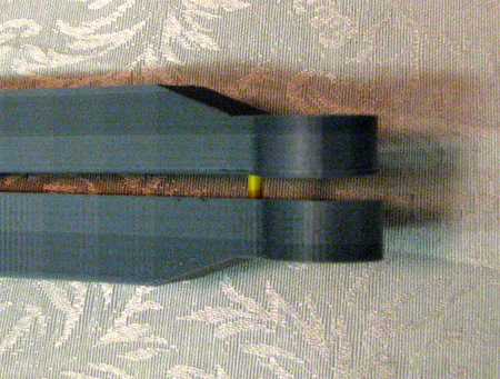
 once you've checked the joints separately it's time to test fit all three points. |
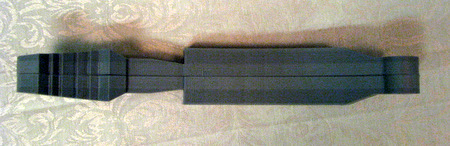 it should take very little pressure to get a tight fit. When you clamp the parts during gluing remember they are NOT solid. Use just enough pressure on the clamp to hold things in place. You do not want to crush the parts. |
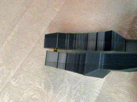
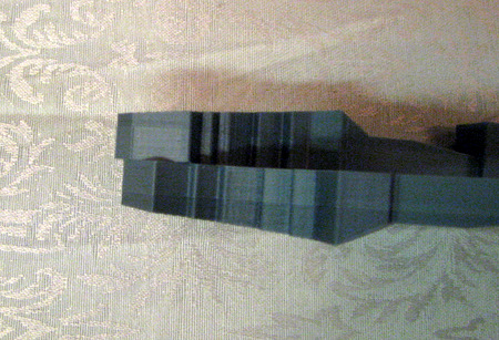
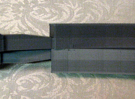
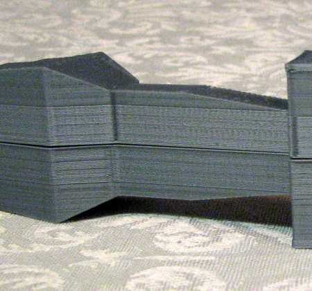 The banding changes because the parts are printed using a smaller layer height on the sections that taper. This reduces the "Stair Stepping" effect. |
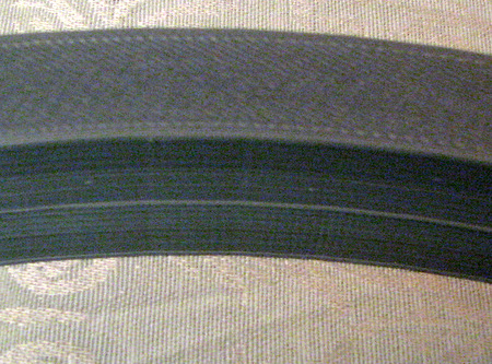 there will be a slight edge at the joint in the middle where the first layer extends out beyond the edge of the part. You can remove that either before, or after, you glue the parts together. |
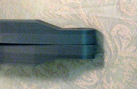
| Once the halves are glued together you can mount them in the arm boxes. The hole at the pivot point is nominally 1/4 inch but will be undersized. Carefully drill it out to accomodate a 1/4 inch shaft. | |
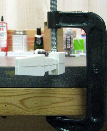
 Above: I assembled an early prototype print. It didn't have the alignment pins or the finer layer height. Note the bolt to align the pivot point. I used Weldon 16 to glue the two pieces together. Right: you can see the glue joint. I used a C Clamp to hold the arm to my workbench |
 |
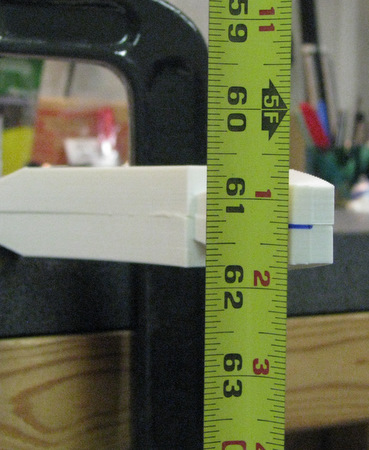 I hung a tape measure from a ceiling rafter to provide a visible reference |
 then I hung a weight from the tip of the arm. I read the deflection at 5/8 of an inch. |
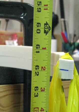
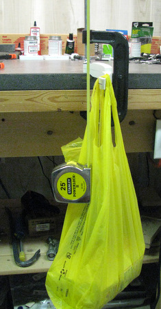 Here's a longer view of the test setup with the weight in the bag |
 And In the Bag, 5Lbs of Sugar!!! |
| What
have we proved? 3D printed utility arms will flex about 5/8 of an inch
under a 5lb load. That dosn't make them indestructable. But it does show they are not fragile. For my 3D Printed Parts Price List click here |
|
| Home |