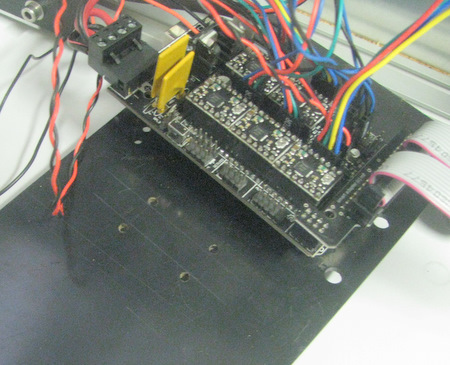
 The
fan
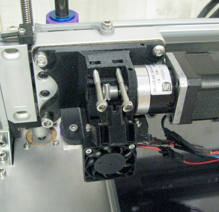
has been removed, the LCD cable is in place and new mounting holes
have been drilled for the fan
The
fan
has been removed, the LCD cable is in place and new mounting holes
have been drilled for the fan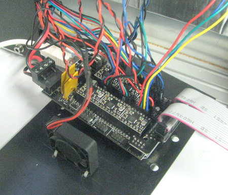
Fan mounted using small ty-wraps.
A1 Electronics
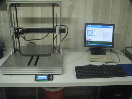
At this point, to proceed further with the assembly I need to be able to turn the printer on, see it report it's status, and give it commands from a PC to move the various axis and turn on the extruder and bed heaters.| The
fan
has been removed, the LCD cable is in place and new mounting holes
have been drilled for the fan |
Fan mounted using small ty-wraps. |
 |
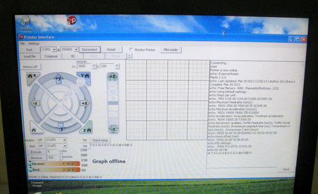 Pronterface connects to the RAMPS @250000 baud and reports everything OK. At this point, the RAMPS is being powered from the USB cable. |
||||||||||||||||
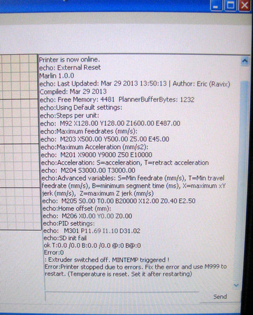 |
However,
when I turn on the power, I get an immediate error message: "Extruder
switched off. MINTEMP triggered!" I used Google to search for this error message. What it's trying to tell me is that the RAMPS board isn't reading the extruder thermistor properly. Unfortunately, there isn't any documentation on how the A1 is wired up. If you Google RAMPS Documentation you can find a diagram showing what all the connection points on the RAMPS board are for as well as a wiring diagram. NOTE: my RAMPS board was wired differently in that the two Z stepper motors are driven from Z and E2 rather than both being driven from Z as shown on the wiring diagram noted above. I pulled the Thermistor connector at the RAMPS board and measured with an Ohmmeter. There was an open circuit. I measured at the J-head 121K ohms (close to the 126K ohms that I measured for the bed thermistor). Clearly something was not making a connection. |
||||||||||||||||
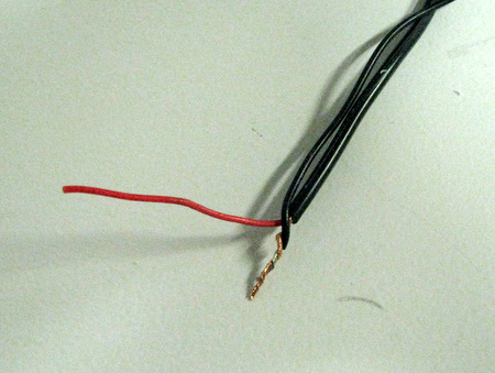
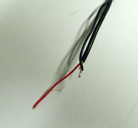
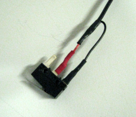
The J-Head Connector has 4 wires
The mating Connector is wired
|
So now we know the source of the problem. The question is how best to fix it. Eric in TL support was asked if it would be feasible to swap the female connector pins in the mating connector. Or if they could supply a replacement cable. I never saw a response. After waiting a day or so I went ahead and swapped the pins. It fixed the problem. TL - Areas for improvement. You need to test wired assemblies to make sure they are correct. Clearly this A1 was never powered up. Support needs to respond to customers with system that are not functioning. |
 |
While you are waiting for
your extruder to warm up loosen up the bolts that hold the idler
bearing against the extruder hub so that you can see the hob move. Find the Pronterface box that says "Extrude" if should be set to 5mm. You can increase that to 20mm so the hob will move for a longer time. When the extruder is up to temp, click on "Extrude". If you are too early you'll get an error message, otherwise the Hob should rotate. Hopefully, it's rotating so that it will draw fiber Down from above and push it into the extruder barrel. If not, your extruder is reversed. To fix a reversed extruder, With the Power OFF!!!, the easiest thing is to remove the 4 pin connector at the RAMPS E0 connector, turn it around and re-install it. |
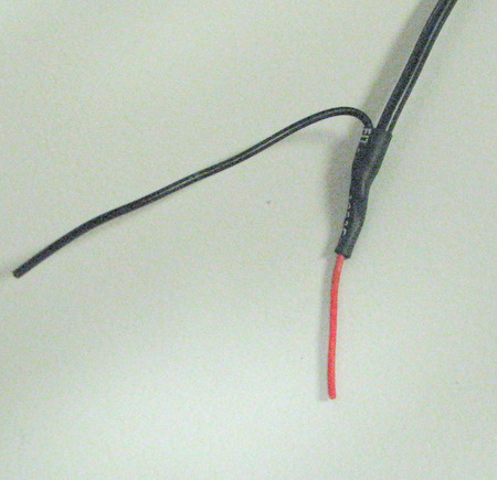
 Start by removing the outer sheath and twisting the shield wires together. Remove about 2 in of sheath, cut the shield to about 1/2 in. Twist with a piece of light gauge wire ( I reused some of the existing End stop wire). |
 Solder the wires and cut short. |
 |
Left:
put a short piece if heat shrink over and shrink in place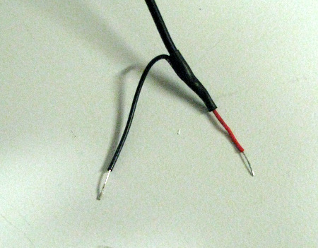 then cut the wires to equal lengths, remove about 1/4 in of the insulation and tin the bare wire. |
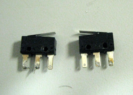 Prepare the switches by removing the old wire and solder. If your switches are very tight on the bolts you might want to slightly enlarge the holes. Be careful not to expose the terminal to the bolt. |
 The center switch terminal is the normally open one and goes to the center conductor. The outer terminal is the common and goes to the shield. Don't forget the heat shrink. Solder the wires. |
 |
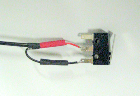
Left:
Completed switch wiring with shrunken insulation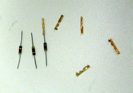 You will need 3 1/4 watt 4.7k ohm resistors. cut the leads to about 1/2 inch. Crimp on a mating contact. If you are not using a crimping tool you might want to solder the contact. |
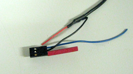
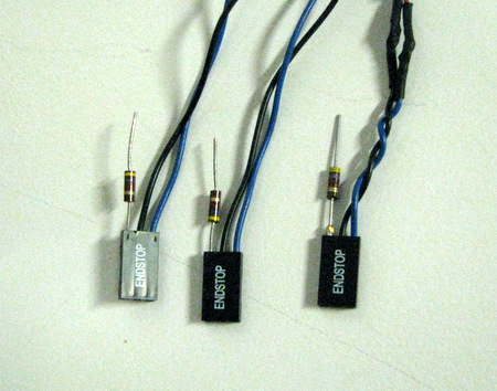 Cut the two non-shielded end stop connectors to a few inches of wire. For the shielded endstop by cut only the signal wire. |
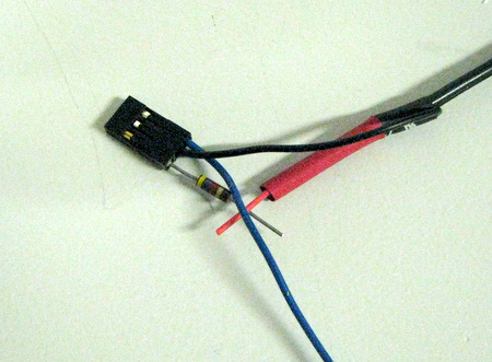
 Connect the ground wire (black, center pin) to the cable shield & solder. As before, insulate with heat shrink tubing |
 Above: Cut a piece of shrink tubing so it will completely cover the resistor. Right: shift the tubing so it's over the signal wire of the cable. You are going to solder the two signal wires (cable and connector) to the top end of the resistor, |
 |
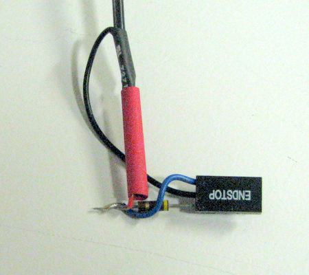 |
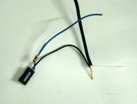
Left:
trim the blue wire to length. Remove the insulation from both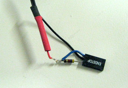 Twist, solder together, then slide the tubing in place and shrink. |
| Home |